How do you read mechanical engineering symbols?
They are often in the bottom right-hand corner of the drawing/part….Information Blocks
- The name and address of the company who produced/ owns the drawings.
- The part number and description.
- Mass.
- Material.
- General tolerances.
- Units.
- Finish.
- Projection details.
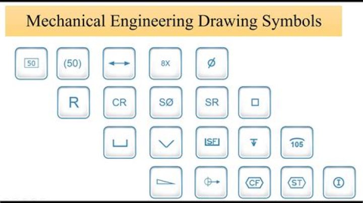
What are engineering drawing symbols?
Engineering Drawing Symbols Basic types of symbols used in engineering drawings are countersink, counterbore, spotface, depth, radius, and diameter.
What are mechanical engineering elements?
Most of the core streams of Mechanical Engineering, viz., Thermal Engineering, Material Sciences and Manufacturing Sciences including latest technologies such as CNC, Robotics, Automation, etc. have been addressed with a perfect balance.
What is the symbol for chamfer?
CH
Engineering drawing abbreviations and symbols
| Abbreviation or symbol | Definition |
|---|---|
| CH | chamfer |
| CHAM | chamfer |
| CI | cast iron |
| CL or ℄ | centreline or centerline; class |
What does R mean in a drawing?
Radius
The “R” represents a Radius, and usually on the print it will call out the size or full.
What is 1st angle and 3rd angle projection?
To get the first angle projection, the object is placed in the first quadrant meaning it’s placed between the plane of projection and the observer. For the third angle projection, the object is placed below and behind the viewing planes meaning the plane of projection is between the observer and the object.
What does R mean in drawing?
Use of just the “R” with no associated size callout is generally intended to mean “full radius.” A word about Y14. 5M: Unless it’s called out on the drawing, or otherwise contractually agreed to, it has no standing.
What is steam in EME?
INTRODUCTION STEAM GENERATOR OR BOILER A steam generator or boiler is usually a closed vessel made of steel. Its function is to transfer the heat produced by the combustion of fuel to water and ultimately to generate steam.
How do you classify engineering materials in EME?
Basic Classification of Engineering Materials
- Metals. Metals are polycrystalline bodies which are having number of differentially oriented fine crystals.
- Non-Metals.
- Difference between Metals and Non Metals.
- Other classification of engineering materials:
- Metals and Alloys.
- Ceramic Materials.
- Organic Materials.
What is a GD symbol?
Geometric Dimensioning and Tolerancing (GD) is a language of symbols and standards designed and used by engineers and manufacturers to describe a product and facilitate communication between entities working together to produce something.
What does R Full mean?
FULL R means Full Radius.
What is 1st angle method?
In the first angle projection, the object is placed in the 1st quadrant. The object is positioned at the front of a vertical plane and top of the horizontal plane. First angle projection is widely used in India and European countries. The object is placed between the observer and projection planes.
How do you read 1st and 3rd angle drawings?
The difference between first and third angle projection is in the position of the plan, front and side views. In third angle, what you see from the right would be drawn on the right. In first angle, the view from the right would be projected through and drawn on the left.
What is efficiency of boiler?
Definition of Boiler Efficiency is “The percentage of the total absorption heating value of outlet. steam in the total supply heating value.” In other word, it is a rate how the boiler runs efficiently.
What do mechanical engineers do list?
Mechanical engineers design power-producing machines, such as electric generators, internal combustion engines, and steam and gas turbines, as well as power-using machines, such as refrigeration and air-conditioning systems. Mechanical engineers design other machines inside buildings, such as elevators and escalators.
What is drawing in mechanical engineering?
Mechanical engineering drawings are technical and skilled drawings that help define and illustrate specific mechanical requirements and processes. They are engineering drawings specifically for mechanical purposes. These technical drawings help communicate problems and solutions that mechanical engineers experience.
What are the most common symbols in engineering?
Basic types of symbols used in engineering drawings are countersink, counterbore, spotface, depth, radius, and diameter. Here are more commonly used engineering drawing symbols and design elements as below.
How are welding symbols used in Mechanical Engineering?
The engineering drawing example Welding symbols is included in the Mechanical Engineering solution from Engineering area of ConceptDraw Solution Park. Mechanical design is a labour-intensive process.
What are the abbreviations for mechanical and electrical systems?
RADIATION SYMBOLS PIPE FITTINGS REFRIGERATION VALVES/FITTINGS VALVES HVAC PIPING TEMPERATURE CONTROL/MONITORING FIRE PROTECTION SYSTEM MEDICAL STEAM PIPING DUCT SYMBOLS PLUMBING MECHANICAL / PLUMBING SYMBOLS AND ABBREVIATIONS ABBREVIATIONS DRAWING NOTATIONS SECTIONS AND DETAILS NORTH FIRST FLOOR PLAN – MECHANICAL DEMOLITION NORTH
Are there any stock photos of Mechanical Engineering?
41,650 mechanical engineering logo stock photos, vectors, and illustrations are available royalty-free.